Recently 3D printing on printers has become very popular, but the equipment is expensive. Not everyone can afford such a luxury. A simple 3D-printer from DVD drives can be assembled with your own hands, it will cost quite cheap. At the same time it will allow you to print a variety of plastic parts at home.
What do you need for assembling?
Parts for the homemade 3D printer can be found in an old computer – CB/DVD drives. Some elements will have to buy, but their cost is not very high. For the assembly you will need:
- DVD drives – 3 pieces.
- A SUNFOUNDER Mega 2560 R3 ATmega2560-16AU with Arduino – 1 pc. It is better to buy it. The price does not exceed 10-12 dollars.
- The Hobbypower A49988 motor driver for the Reprap 3D printer – 4 pcs. It will cost about $9-10.
- STEPPERONLINE Nema 17 stepper motor for DIY CNC 3D printer – 1 pc. Its cost with wires for connection is about $12-14.
- QWORK extruder module – 1 pc. The cost is about $8-9.
- Power supply with parameters: 12 V, 5 A.
- Cables, wires and connectors.

Beforehand it is necessary to prepare assembly tools and measuring tools: an electric drill, a hacksaw, an electric jigsaw, a soldering iron, pliers, wire cutters, a screwdriver set, a tester, a level, a ruler, a caliper.
Step by step instructions for assembly
As a base for the printer you can use a sheet of plywood or textolite 18-20 mm thick. It is cut to the required size. You make a marking of the base. Holes are drilled for fastening the supporting elements of the structure. Assembly is divided into a few basic stages.
The X, Y and Z axes
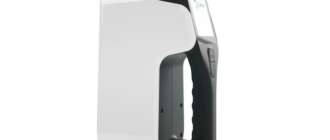
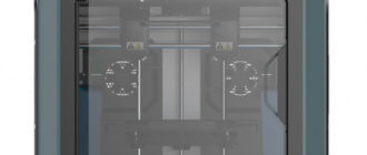
The assembly of the printer begins with mounting the frame of the device in the form of vertical poles made of wood or aluminum profiles. They are fastened to the base. Next, the Z axis is formed from a single DVD input (photo 1). The plateau is mounted vertically. For the Y-axis the input is fastened sideways. A similar DVD input is attached to this input for X-axis movements. The result is a system (photo 2) that allows the extruder head to move in two directions parallel to the base and in the vertical direction, changing the gap between the nozzle and the work surface.
The “brain” part consisting of Arduino Uno, CNC Shield, A49988 drivers and other actuator controls is fixed on the back wall of the input. Their connection is ensured. On the Z-axis, the extruder module is mounted. A Nema 17 stepper motor is mounted on top of the extruder to feed the plastic (filament). It is better to connect it through a reducer, assembled from standard gears for a 3D printer.
Power supply

The next step is to install the actuator power supply. It is important to connect it so that it provides direct power with a switch to the stand. The two wires of the block (12V and GND) are used to power the controller. Any computer power supply is good, e.g. 20pin PC power supply.
Testing of motors
The motors can be prepared for the new environment with the help of special programs. In particular the Arduino 23 version is quite suitable. After installing the Arduino 23, the firmware for the motors is uploaded. It is possible to choose Marlin. The computer is connected to the CNC controller with a USB cable. Then the desired serial portal under Arduino tools IDE is selected. The firmware opens and then the configuration parameters are displayed: #define MOTHERBOARD 3, Thermistor 7 and PID, and step 9 to one to configure the controller.
Setting up control via computer

To control your printer, you need to install software. One of the easiest and most reliable programs is Repetier Host. The slicer is used to link object sections to layers and generate printer G-code. The cuts are configurable in terms of layer height, print speed, and other parameters. Slicer configurations such as Skeinforge or Slic3r can be used.
Power Adjustment

The next step is to test the motors in order to adjust the current and intensity. The software is started and matched to the controller. Next you can switch to manual control of the motors. First of all the maximum current value is set, at which they will not heat up. The adjustment is made for each axis separately. A multimeter set in amplifier mode is used for measurements.
Again the computer is connected and the current rise corresponding to the motor step is checked. With the handheld potentiometer the current limits are set for each axis. The current limits are: 80 mA for the board, 200 mA for X and Y axis steppers, and 400 mA for Z axis. A current limit of about 400 mA is also set for the extruder.
Designing the structure
In the design of the printer, it is important to ensure that the frame and guides are strong enough and workable. They are the most important structural elements. They can be 3D printed using templates or laser-cut using Auto Cad from an acrylic plate that is about 5 mm thick. This technology makes it possible to create a structure without glue and screw connections.
Calibration of axes

The downloaded Marlin program is capable of providing standard axle calibration. More precise programs for the homemade printer are not needed. It is important to make sure that all movements correspond to G-code distances. The task is simplified by the fact that all axes use the same threaded studs of the DVD drives.
The calibration determines the number of motor steps per 1 mm displacement. The parameter depends on the speed of the motor and the radius of the pulley. The setting is repeated 3-4 times for increased accuracy.
Extruder Setup

The extruder module is attached to the movable element of the frame, which can be moved on slides in vertical direction from the Z axis drive. The feeding of the plastic filament is carried out by a NEMA 17 motor, whose shaft is connected to MK7/MK8 gears. The appropriate drivers are installed to control the motor: the idle extruder, the body extruder, and the laser. The plastic is fed into the heating chamber of the module via a Teflon tube. The main motor is securely attached to the frame. Its calibration is mandatory. For this purpose, a controlled piece of filament is fed, which must correspond to a certain travel distance (e.g. 10 cm).
Test print

After the assembly is complete, a test print of the part is made. Usually a 1.75 mm diameter PLA filament is used. The test program is activated in Repetier. It is recommended to start by printing a standard cube with a side of 10 mm. Such a part will be made quickly and without unnecessary waste of material, allowing you to estimate dimensional accuracy in all three axes. To print, the extruder temperature is set at 190-210 °C.
Before printing begins, the starting point is set, i.e. X, Y, Z = 0. The gap between the nozzle and the work surface is set with a sheet of paper. The Z-axis adjustment ensures a gap equal to the sheet thickness (Z=0).
What do I pay attention to in order to avoid mistakes?
When making a 3D printer with your own hands, you should take into account such nuances:
- The main savings are achieved by using DVD drives to provide movements on the axes and the construction of a homemade frame.
- You should not skimp on the extruder, the main stepper motor and the gearbox for it. It is necessary to buy standard, new products designed for 3D printers, because the performance of the entire device largely depends on them.
- The power (current) adjustment is carried out with great care to avoid overheating of the motors.
- The printing quality depends to a large extent on the correct calibration of all the axes. It must be carried out before each start-up of the printer.
- It is important to make sure that the printing area is perfectly level.
The guides must be machined to a sufficient degree of accuracy to allow the head to move freely in all axes.
Use a standard plastic (usually PLA) for printing. The temperature in the extruder should match the brand of laminate.
With careful assembly and the use of quality parts, a workable 3D printer can be made. Its accuracy is inferior to factory models, but it will be quite sufficient for printing products with practical applications. Home craftsmen have proven that a homemade printer is quite capable of replacing expensive equipment at home.